pillScope Plus: STM32F401 Black Pill educational oscilloscope
A self-contained scope on an STM32F401 Black Pill with a colour TFT, on-screen measurements and UART export.
Photos
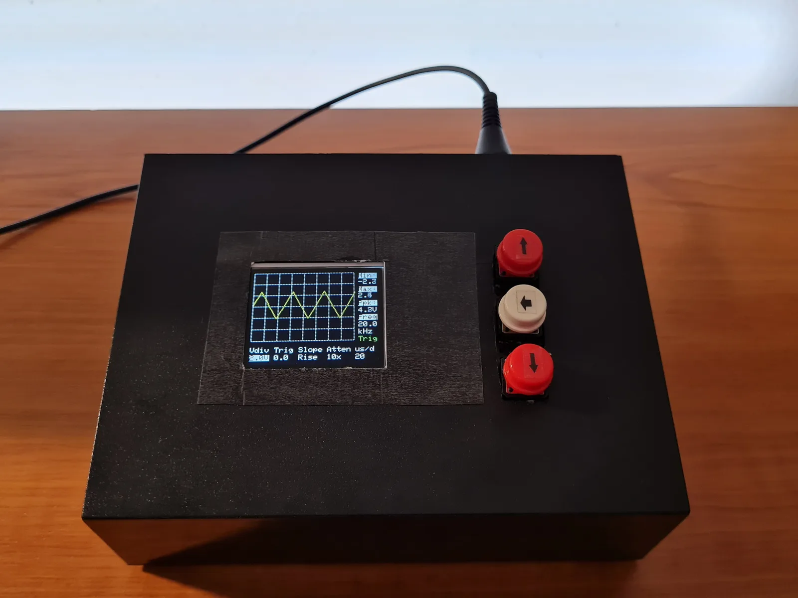
Photos: tvlad1234/pillScopePlus
Key Facts
- Chip: STM32F401CC Black Pill
- Display: 128x160 ST7735 TFT
- Sample rate: 1.6 MSa/s
- Input: +/-3.3 V, 1 MOhm
About This Project
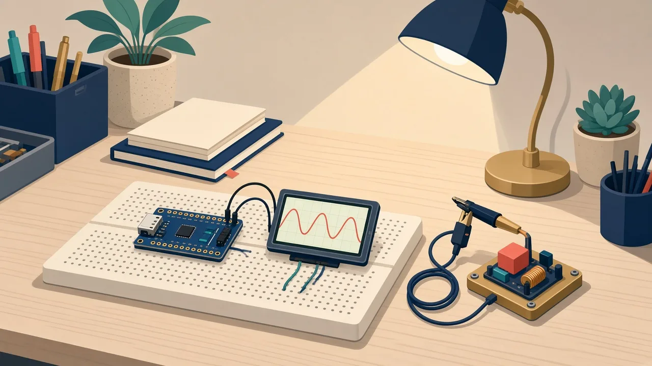
pillScope Plus is an educational digital storage oscilloscope built around the STM32F401 Black Pill and a 128x160 ST7735 colour TFT. It samples at up to 1.6 MSa/s, shows min/max/peak-to-peak and frequency on screen, and can send captures to a PC for viewing in TekScope. The front end uses an LM358 (rail-to-rail recommended) and three buttons. Designed to teach how scopes work while remaining usable in a lab.
Source & Attribution
Parts Needed
- STM32F401CC Black Pill
- 128x160 ST7735 TFT display
- 3 pushbuttons
- LM358 dual op-amp (a rail-to-rail part is better)
- 2x 68kΩ and 2x 500kΩ resistors (offset and attenuator)
- 5V power supply
- Optional: opto-isolated USB-UART adapter, BNC connector
- ST-Link or USB DFU for flashing
Steps
- 1
Build the front end
Following the schematic, wire the op-amp input stage. The 68k resistors set a 1.65V virtual ground and the 500k resistors attenuate the input. The output goes to PA0 (ADC1_IN0).
- 2
Connect the display and buttons
Connect the ST7735 to SPI1: SCK on PB3, MOSI on PB5, CS on PB12, RST on PB13 and DC on PB14. The buttons go on PB9 (Up), PB8 (Select) and PB7 (Down).
- 3
Build and flash
Compile with make (the source is in Core/Src) and flash the binary with an ST-Link or the Black Pill's USB DFU bootloader.
- 4
Calibrate and measure
Run the auto-calibration from the UI before use. Because of the virtual ground, the scope and the circuit under test must not share a ground. Use an isolated supply or the opto-isolated UART adapter.
- 5
Save captures
Send 's' over UART for CSV output (TekScope-compatible), or 'S' for raw data that the companion app streams to TekScope in near real time.
Not included: 3D-printed case, wire, solder, USB cable
Related Projects